Die-wall stress measurement
Posted: 20 May 2005 | | No comments yet
Many of the physical factors that affect tablet quality are formed during compaction. Thus, the accurate measurement of tablet compaction will help researchers to better understand compaction and die-wall stress measurements are a critical aspect of being able to measure and understand the three-dimensional nature of compaction.
Many of the physical factors that affect tablet quality are formed during compaction. Thus, the accurate measurement of tablet compaction will help researchers to better understand compaction and die-wall stress measurements are a critical aspect of being able to measure and understand the three-dimensional nature of compaction.
Insights from die-wall stress data give important information about critical properties1 such as die-wall friction2, tool wear and capping and lamination3. This information can aid the selection of excipients and press operating conditions that optimise a formulation and production. In addition, the radial transmission of the applied axial punch force to the die wall is needed to fully understand the fundamental mechanisms of tablet compaction; in fact, a complete theoretical elastic, viscoelastic or plastic analysis can not be done without this data.
Tablets are formed by reducing the volume of a set of autonomous particles until they are consolidated into a solid mass. The resulting stress versus time profile for a typical compaction process is shown in Figure 1. The stress generated during compaction is a consequence of a reduction in powder bed volume. In other words, the tablet machine applies a displacement to the powder bed and the observed stress is the result of this displacement, which reduces the powder bed volume. As a consequence of this volume reduction, the powder bed undergoes a series of semi-discrete stages. The first stage is the loading phase, which starts when the leading edge of the punch head contacts the compression roller. The punch head is shaped liked a torus (doughnut with hole in middle) with the top covered by a flat plate, see Figure 2 and it is the location of the compression roll on the punch head that determines the phase of compaction. As the punches come together the powder reversibly rearranges itself into a smaller volume, see Figure 1. This continues until the powder bed can no longer reversibly rearrange by tighter packing; at this point the particles begin to deform. Initially, the deformation is elastic, which continues until the elastic limit or yield point is reached. At this critical point, the particles also begin to deform irreversibly and fracture. The type of deformation and/or fracture depends upon the material properties of the powder and the speed of compression. The punches continue to compress the powder bed until the dwell phase is reached. The dwell-phase is the point where the compression rollers rest on the flat portion of the punch head, see Figure 2. It should be noted, this definition is based upon punch movement and not half peak height as in some engineering definitions. Thus, the punch displacement is held constant and hence the powder bed volume is constant in theory, see Altaf et al. for a more detailed discussion of this phase4. In this phase some of the stored energy is dissipated by viscoelastic and plastic deformation and is important for bond formation in the tablet4. The unloading phase begins once the compression roller leaves the punch flat, see Figure 2. In this phase, the stored energy in the tablet is released; it is this energy release that causes the tablet to expand and push the punches apart. For some materials, elastic recover can cause significant tablet expansion during unloading, which can result in tablet capping and lamination. At the end of unloading when the punch stress is zero, the viscoelastic stress relaxation phase begins. During this phase internal viscoelastic and plastic flow reduce the residual die-wall stress.
The simplicity of uniaxial compression obscures the fact that the process is really three dimensional and even thought the die-wall isn’t actively moving the constraint which it applies to the powder bed during tablet compaction is significant to final product quality. As the axial punch stress is applied to the powder bed, some of this is transmitted axially down through the powder bed but some of the stress is transmitted radially to the die-wall, through a chain of contact forces between adjacent particles. The nature of the deformation and fracture through the chain of particle contacts is critical to the formation of a tablet’s mechanical properties during compact. These are the processes that bring the particles into close physical contact, which is essential for interparticulate bond formation. For further information on these factors refer to: 5,6.
Transducer Principles
Die wall-stress can be measured by a transducer; a transducer is a device that converts energy from one form to another. For die-wall-stress measurements a unit of mechanical energy applied to the die wall is proportionally converted to a unit of electrical energy that can be measured by a data acquisition system; for a general review of transducers and data acquisition systems see Dally7 and Watt6. Before discussing specific systems a general review of transducer design principles is helpful.
These design concepts can best be illustrated by a simple design example; for a detailed discussion see Collins8,9. While numerous factors must be considered, the essential design criteria are: sensitivity (minimum detection limit), measurement range (maximum reading at full scale reading) and response linearity. To illustrate these concepts we can start with a simple mechanical scale. Readers may have sufficient personal history to remember when scales had springs with mechanical linkages to an analog readout. When the load was applied the spring deformed in accordance with Hook’s law:
σ = κ ε (1)
where the stress (σ) is the force per area and the strain (κ) is the change in length divided by the original length and ε is the elastic modulus or spring constant. Listing of material properties are available in handbooks9,10. In essence, this law states that for a given spring the change in length is proportional to the applied force. The strain is often expressed as microstrain (με), which is the stain multiplied by 106 and has units of length/length, in other words it is a dimensionless unit. The stress is often expressed in pounds per square inch (psi) or N/m2 multiplied by 106 (MPa).
For example, given a transducer such as that shown in Figure 3 with properties given in Table 1, the minimum detection limit and full scale reading can be calculated using Hook’s law. For these calculations, it will be assumed that the data acquisition system has a minimum detection limit of 0.05 με and a full-scale reading of 1000 με; these constraints are primarily based upon the inherent properties of the construction materials and data acquisition system, for a more complete description see Dally7,9. In this example, the modulus and the cross sectional area of the spring – i.e. its geometry – and material properties were varied. As shown in Table 1, for a given data acquisitions system these two factors control transducer performance. For the high modulus spring, when the cross sectional area is doubled the full scale reading went from 25 kg to 50 kg, but the tradeoff is that sensitivity is halved from 1.25 gm to 2.5 gm, which is significant when trying to design a sensitive transducer. If the modulus, i.e., the construction material, is changed from 1.0 GPa to 0.1 GPa then the sensitivity is proportionally increased by a factor of 10, but the tradeoff is that the full scale reading is reduced. Today most scales have digital readouts where the mechanical linkage has been replaced by a bonded electrical resistance strain gage. Bonded electrical resistance strain gages are thin alloy foils that are actually bonded to a surface by an adhesive such as epoxy and their electrical resistance changes in direct proportion to the surface strain7. These gages are easier to integrate into a computer-based data acquisition system; this allows the automation of data recording and makes real time measurements possible. However the transducer design principles remain the same, just the strain sensors and data acquisition system have changed.
In summary, for a transducer to have a measurable signal the strain at the gage site must exceed the minimum detection limit of the strain gage and data acquisition system. Because reducing the transducer (spring) thickness concentrates the forces into a smaller area, which increases the strain and hence the signal output, the transducer must be thin enough (proper design geometry) so that the forces generated during compaction produce a measurable strain. Yet, the transducer must be thick enough to withstand the forces generated during loading without yielding or rupturing. Thus, an optimally designed transducer must balance these competing demands of signal output and material failure.
Classification of die-wall stress measurement transducers
Because it is the design geometry and associated strain gage arrangement that determines the performance characteristics of a transducer, there have been many different designs and special gage configurations developed for the optimisation of die-wall stress measurement. Figure 4 shows the scheme that will use in this paper to classify die-wall stress transducers. An example of a non-traditional method is Ridgway’s photoelastic die11; this and other miscellaneous systems are discussed by Watt6. Aside from these miscellaneous methods, the first categorisation is between flexible and inflexible. The flexible die-wall transducers have traditionally been used in geology, soil science, by engineers studying powders and occasionally in pharmacy12. However, as more engineers investigate pharmaceutical powders, these systems may be come more popular. For an example see Abdel-Hadi, et al.13. With these systems, the powder can expand laterally during compression, which generates a pressure in the surrounding fluid that can be measured by a pressure transducer. This has the advantage that the experiment gives more data about the radial expansion, which would not be possible with an inflexible die wall. This added data is needed to fully characterise certain material properties like anisotropy.
By far the most popular methods for die-wall stress measurement in the pharmaceutical sciences are ridge die-wall systems. Examples of these systems are: 14,15,16,17,18,19,20,21,22,23,24. The earliest transducer design for the measurement of die wall stress was Nelson’s three-punch die14, followed by Windheuser’s segmented die15.
Segmented die
The segmented die, shown in Figure 6, has a cut-away geometry comprised of two factors: the cutting angle (φ) and the effective die-wall thickness (t). By reducing the die wall thickness in selected regions the stress is concentrated in these regions, which increases the strain at the outer die-wall making the transducer more sensitive to die wall stress23. To optimise transducer performance the segmented die geometry, i.e., die wall thickness and cutting angle and strain guage (sensor) configuration have been modified in past years by trial-and-error.
Even though sensitivity has been optimised for the segmented die, there are still two major concerns; the effects of tablet height and tablet position within the die on output signal23. These two factors can make calibration and data interpretation more difficult because they interact, causing the transducer to have a nonlinear output signal23. To better understand the characteristics of the segmented die, Finite Element Analysis (FEA) can be used to simulate the performance of the transducer. Basically, FEA is a numerical method that divides a mechanical component into many small body elements, called finite elements, for the purpose of stress/strain analysis. For more information on FEA refer to Cook et al.,25, Rao26 and Spyrakos27. The FEA results show the Von Mise stress contours in Figure 6; for elastic bodies there is a one-to-one correspondence between the Von Mise stress and the actual stress and strain27. These plots reveal what happens to the stress/strain distribution when a tablet of the same height and same radial die wall pressures has its location varied in the die. This shows that for a given stain gage location the measured die-wall pressure will change due to the location of the tablet and not the actual radial pressure of the tablet, which is the parameter of interest. Figure 6 shows how the stress contours radiate out in a circular fashion from the area of contact between the die wall and tablet. As a result, the surface strain on the outer die wall varies with location; therefore, signal output will also vary with strain gage location. In addition, because the stress contours radiate out from the area of contact between the tablet and die wall, the stress distribution (for a fixed pressure) at the outer die wall will also change when the area of contact between the tablet and die wall changes; therefore, signal output will also change when the height of the tablet changes. These results help to explain the well known but often under appreciated fact that the output signal for a segmented die with a fixed tablet height is linear, but when the tablet height is varied (as in tablet compaction) the output becomes nonlinear.
To address these concerns, the strain gage configuration has been modified to reduce the effect of tablet height and position on signal output. For example, Hölzer and Sjögren22 found that the die-wall signal increases linearly with tablet height. To compensate they used the area of contact between tablet and die wall to normalise the output signal. Huckle and Summers21 improved die-wall stress measurement by averaging the output signal from multiple gages placed on the cut-away portion of the die. This strain gage arrangement reduces the dependence of die-wall stress measurements on tablet height. Cocolas and Lordi19 developed another approach that used the height of the tablet to normalise the summed response from four piezoelectric force transducers placed in a spiral arrangement around the die bore. All of these methods greatly improved the original segmented die design; however, measurements from these systems are based upon averaging die-wall stress over the height of the tablet, which neglects changes in die-wall stress that can occur along the height of the tablet during compaction. In addition, transducer calibration is still dependent upon tablet position within the die.
Split-web die
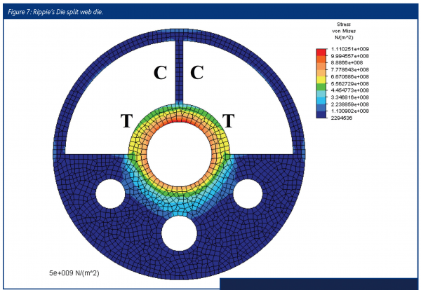
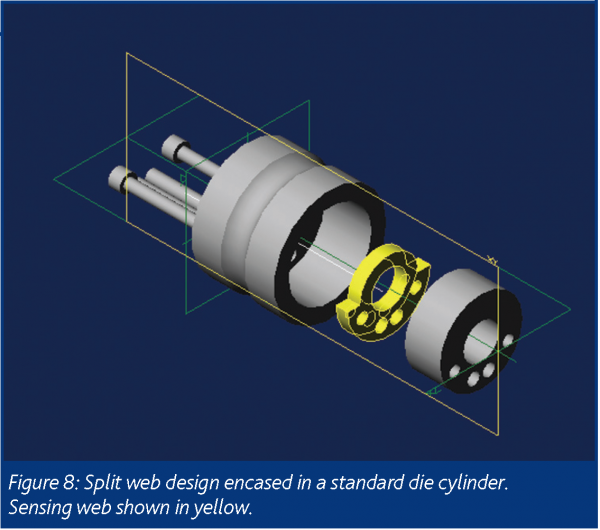
Another approach for improving die-wall stress measurement is the three-layered die developed by Rippie and Danielson18, see Figure 7. By putting strain gages on the thin middle layer, in effect creating a thin sensing web, this design isolates stress measurement to a narrow band around the tablet that gives a much closer approximation to the true stress. In addition, because the stress/strain distribution in the sensing web is completely uncoupled from all other die-wall stresses and strains the die-wall stress measurement is linear and independent of tablet height and position within the die (as long as the sensing web has full contact with the tablet). Thus, changes in die-wall stress with tablet height can be accounted for. Another advantage of Rippie’s three-layered die is signal linearity, see Yeh et al. for a more detailed discussion23. However, a disadvantage of Rippie’s design is that the die table must be modified to accommodate mounting of the transducer. To avoid modifying the die table, Yeh et al.23 propose a split-web die concept that encloses the sensing web in a cylinder, thereby avoiding the sensing web binding caused by the standard die lock-screw, see Figure 8. To obtain the best design, Yeh et al.23 optimised the sensing web configuration using FEA.
Compaction simulator die
The designs shown in Figure 7 and 8 were optimised for a maximum die-wall stress of 120 MPa, which approximates typical production conditions for a rotary tablet press. However, when using a compaction simulator the die-wall pressures can be much higher because of the need to study material properties at very low porosities. Under these conditions the die-wall stresses can be as high as 400 MPa,28,29,30 which greatly exceeds the capacity of the previous design. However, adapting the split-web design to a compaction simulator by just making the die wall thicker would result in a transducer with poor sensitivity, because the high pressures that occur in a compaction simulator would require a very thick die-wall; thus, the design geometry had to be reconfigured. One-way of improving transducer sensitivity is to create areas of tension and compression within the transducer; with this type of geometry greater sensitivity can be achieved. With the cylindrical geometry of the split-web design it is impossible to create areas of tension and compression within the transducer. For a complete description of these considerations, see 7 or 23. Therefore Hoag et al.24 developed a design concept that has a sensing web with two slots that run parallel to the die bore. With this design, the portion of the slot that runs parallel to the die bore is under tension while the edges of the slot perpendicular to the die bore are under compression. With this design, transducer sensitivity is maximised because there are two strain gages placed in the regions of compression and two gages placed in the regions of tension. In addition, the supported arch gives better mechanical strength while still maintaining sensitivity. This slotted sensing web would then be bolted between two plates and this entire assembly would then be mounted in the compaction-simulator die table, similar to the Rippie die shown in Figure 7.
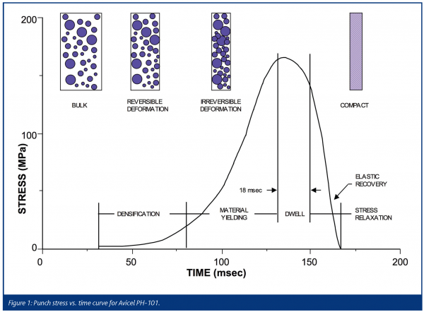

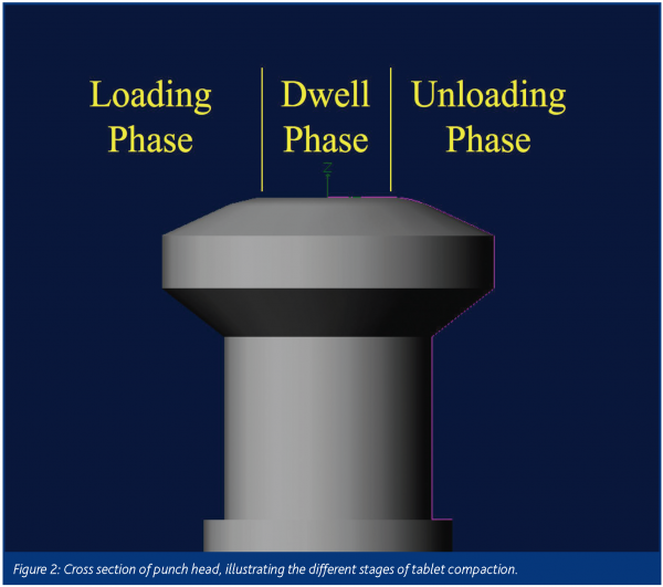

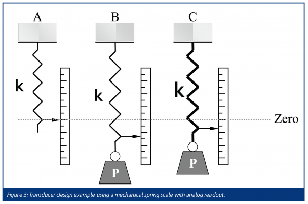

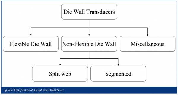

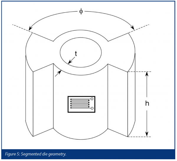

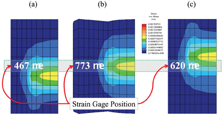

Figure 6: Effect of tablet position on the stress distribution in a segmented die. All tablets are the same height and have the same radial die-wall pressure. Note, the strain (signal output) for a centrally mounted strain gage is different for each tablet position: (a) low, (b) middle and (c) high even though die wall pressure is the same.


References
- Krycer, I.; Pope, D. G.; Hersey, J. A. The interpretation of powder compaction data – a critical review. Drug. Dev. Ind. Pharm 1982, 8, 307-342.
- Hölzer, A. W.; Sjögren, J. Evaluation of some lubricants by the comparison of friction coefficients and tablet properties. Acta Pharmaceutica Suecica. 1981, 18, 139-148.
- Sugimor, K.; Mori, S.; Kawashima, Y. CHARACTERIZATION OF DIE WALL PRESSURE TO PREDICT CAPPING OF FLAT-FACED OR CONVEX-FACED DRUG TABLETS OF VARIOUS SIZES. Powder Tech. 1989, 58, 259-264.
- Altaf, S. A.; Hoag, S. W. Deformation of the Stokes B2 Rotary Tablet Press: Quantitation and Influence on Tablet Compaction. J. Pharm. Sci. 1995, 84, 337-343.
- Alberborn, G.; Nystrom, C. Pharmaceutical powder compaction technology; Marcel Dekker Inc.: New York; 1995; p 610.
- Watt, P. R. Tablet Machine Instrumentation in Pharmaceutics: Principles and Practice; Ellis Horwood Limited: New York; 1988; p 346.
- Dally, J. W.; Riley, W. F. Experimental Stress Analysis, 2 ed.; McGraw-Hill: New York; 1978.
- Collins, J. A. Failure of materials in mechanical design: analysis, prediction, prevention; John Wiley & Sons: New York; 1993.
- Measurements Group, I. Strain Gage Based Transducers; Measurements Group, Inc.: Raleigh, NC; 1988.
- Benjamin, D.; Kirkpatrick, C. W. Metals handbook, 9 ed.; American Society for Metals: Metals Park, Ohio; 1980; p 882.
- Ridgway, K.; Rosser, P. H. The application of photoelastic techniques to a rotary tableting machine. J. Pharm. Pharmacol. 1971, 23, 202S-209S.
- Amidon, G. E.; Smith, D. P.; Hiestand, E. N. Rotary press utilizing a flexible die wall. J. Pharm. Sci. 1981, 70, 613-617.
- Abdel-Hadi, A. I.; Zhupanska, O. I.; Cristescu, N. D. Mechanical properties of microcrystalline cellulose Part I. Experimental results. Mechanics of Materials 2002, 34, 373–390.
- Nelson, E. The physics of tablet compression. VIII. Some preliminary measurements of die wall pressure during tablet compression. J. Am. Pharm. Assn. Sci. Ed 1955, 44, 494-497.
- Windheuser, J. J.; Misra, J.; Eriksen, S. P.; Higuchi, T. Physics of tablet compression. XIII. development of die-wall pressure during compression of various materials. J. Am. Pharm. Assn. 1963, 52, 767-772.
- Conte, U.; Colombo, P.; Manna, A. L.; Caramella, C. La mesure de la force radiale a l’aide d’une matrice divisee: Applications aux problemes pharmaceutiques. Il Farmaco – Ed. Pr. 1977, 32, 551-559.
- Kanaya, Y.; Ando, T.; Asahina, K. A technique for measurements of die wall pressure during tablet compression. Yakuzaigaku 1979, 39, 26-33.
- Rippie, E. G.; Danielson, D. W. Viscoelastic stress/strain behavior of pharmaceutical tablets: Analysis during unloading and postcompression periods. J. Pharm. Sci. 1981, 70, 476-482.
- Cocolas, H. G.; Lordi, N. G. Axial to radial pressure transmission of tablet excipients using a novel instrumented die. Drug. Dev. Ind. Pharm. 1993, 19, 2473-2497.
- Takeuchi, H.; Nagira, S.; Yamamoto, H.; Kawashima, Y. Die wall pressure measurement for evaluation of compaction property of pharmaceutical materials. Int. J. Pharm. 2004, 274, 131-138.
- Huckle, P. D.; Summers, M. P. The use of strain gauges for radial stress measurement during tableting. J. Pharm. Pharmacol. 1985, 37, 722-725.
- Hölzer, A. W.; Sjögren, J. Instrumentation and calibration of a single-punch press for measuring the radial force during tableting. Int. J. Pharm. 1979, 3, 221-230.
- Yeh, C.; Altaf, S. A.; Hoag, S. W. Theory of force transducer design optimization for die wall stress measurement during tablet compaction: optimization and validation of split-web die using finite element analysis. Pharm. Res. 1997, 14, 1161-1170.
- Hoag, S. W.; Muller, F. X. Force transducer design optimization for the measurement of die-wall stress in a compaction simulator. J. Pharm. Parmacol 1999, submitted.
- Cook, R. D. Concepts and applications of finite element analysis, 2 ed.; John Wiley & Sons: New York; 1981.
- Rao, S. S. The finite element method in engineering; Pergamon Press: Oxford; 1982.
- Spyrakos, C. C. Finite Element Modeling in Engineering Practice; Algor: Pittsburgh, PA; 1994; p 322.
- Roberts, R.; Rowe, R. The effect of punch velocity on the compaction of a variety of materials. J. Pharm. Pharmacol. 1985, 37, 377-384.
- Holman, L. The Compressibility of pharmaceutical particulate systems. An illustration of percolation. Int. J. Pharm. 1991, 71, 81-94.
- Celik, M.; Ong, J.; Chowhan, Z.; Samuel, G. Compaction simulator studies of new drug substance: effect of particle size and shape, and its binary mixtures with microcrystalline cellulose. Pharm. Dev. Tech. 1996, 1, 119-126.


